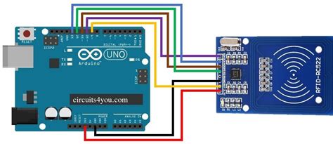
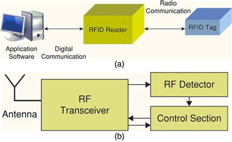
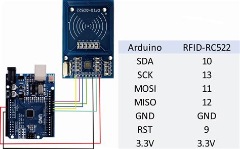
rfid card reader circuit diagram The RC522 module has a total of 8 pins. This module supports various communication protocols and each pin has a different function for each communication protocol. The pinout of a RFID Reader moduleis as follows: SDA SCLI2C Communication pins. DATA and CLOCK. SS SCK MOSI . See more The NFL has announced the full schedule for the wild card and divisional round .
0 · rfid with Arduino code
1 · rfid tag block diagram
2 · rfid schematic diagram
3 · rfid rc522 with arduino
4 · rfid rc522 interfacing with arduino
5 · rfid rc522 Arduino Mega 2560
6 · rfid circuit diagram explanation
7 · how to connect rfid arduino
Security risks: NFC tags themselves are typically very secure. They can only hold a small .
The RC522 module has a total of 8 pins. This module supports various communication protocols and each pin has a different function for each communication protocol. The pinout of a RFID Reader moduleis as follows: SDA SCLI2C Communication pins. DATA and CLOCK. SS SCK MOSI . See moreThe Schematic diagram for the RC522 moduleis given below. The circuit consists of bare minimum components. As we know the main component is the MFRC522 chip. The remaining components form the EMI filter along with the matching circuit . See moreWhat is an RFID used for? RFID tags are a type of tracking system that uses radiofrequency to search, identify, track, and communicate . See more
The RC522 RFID module is based on the popular MFRC522 RFID reader chip from NXP These modules are cheap and available from most . See more
The RFID system is comprised of two components: the RFID reader and the tags. They are also called PCD (Proximity Coupling Device) and PICC (Proximity Integrated Circuit . See moreThis section is written for RF coil designers and RFID system engineers. It reviews basic electromagnetic theories on antenna coils, a procedure for coil design, calculation and . The RFID card reader circuit diagram is a great way to introduce the world of Radio Frequency Identification readers. RFID readers are an invaluable tool in today’s world, .
In this tutorial, we discussed how the RFID Reader Module works and how we can use it with Arduino. For Interfacing RFID Reader Module RC522 with Arduino, we have .RC522 Pinout Diagram. All the pins of MFRC/RC522 RFID card Reader are: Power/Reset Pins. SPI and UART Communication Pins. RC522 RFID Reader Features. RFID RC522 uses .This section is written for RF coil designers and RFID system engineers. It reviews basic electromagnetic theories on antenna coils, a procedure for coil design, calculation and . The RFID card reader circuit diagram is a great way to introduce the world of Radio Frequency Identification readers. RFID readers are an invaluable tool in today’s world, .
Learn how to use RFID NFC RC522 with Arduino, how to connect RFID-RC522 module to Arduino, how to code for RFID/NFC, how to program Arduino step by step. The detail .
rfid with Arduino code

RFID (Radio Frequency Identification) reader circuit diagrams are used in a variety of applications for tracking and identifying objects. Every RFID system has at least one RFID .RFID CARD READER WITH ARDUINO,RFID-RC522 and LCD 16x2: Radio-frequency identification (RFID) uses electromagnetic fields to automatically identify and track tags .
cisco compatible rfid tags
Circuit Diagram For Interfacing RFID with Arduino. n the circuit diagram for this integration, you’ll typically see the RC522 RFID module connected to specific pins on the Arduino board. These . RFID readers can read and/or write data in to the RFID cards (depending on the type of the card). The RFID Reader module used in this project is EM – 18. It radiates a 125 . In this tutorial, we are going to interface RDM6300 RFID Reader Module with Arduino Nano. The RDM6300 RFID Reader is one type of RFID module with a 125 kHz .
In this tutorial, we discussed how the RFID Reader Module works and how we can use it with Arduino. For Interfacing RFID Reader Module RC522 with Arduino, we have .RC522 Pinout Diagram. All the pins of MFRC/RC522 RFID card Reader are: Power/Reset Pins. SPI and UART Communication Pins. RC522 RFID Reader Features. RFID RC522 uses .This section is written for RF coil designers and RFID system engineers. It reviews basic electromagnetic theories on antenna coils, a procedure for coil design, calculation and .
rfid tag block diagram
The RFID card reader circuit diagram is a great way to introduce the world of Radio Frequency Identification readers. RFID readers are an invaluable tool in today’s world, .Learn how to use RFID NFC RC522 with Arduino, how to connect RFID-RC522 module to Arduino, how to code for RFID/NFC, how to program Arduino step by step. The detail .
RFID (Radio Frequency Identification) reader circuit diagrams are used in a variety of applications for tracking and identifying objects. Every RFID system has at least one RFID .RFID CARD READER WITH ARDUINO,RFID-RC522 and LCD 16x2: Radio-frequency identification (RFID) uses electromagnetic fields to automatically identify and track tags .
Circuit Diagram For Interfacing RFID with Arduino. n the circuit diagram for this integration, you’ll typically see the RC522 RFID module connected to specific pins on the Arduino board. These .
RFID readers can read and/or write data in to the RFID cards (depending on the type of the card). The RFID Reader module used in this project is EM – 18. It radiates a 125 .

rfid schematic diagram


clone rfid tag with sdr
chromebook rfid reader sub
This can also be purchased on the above shopping platform. Open the Mtools application. Plug in the ACR122u in your android smartphone with the OTG adapter. Click the “+” Icon. Place the card onto the reader. The card is .Open the payment app and add a credit or debit card. Step 3.1. Choose the default payment app on your Android device. Step 3.2. Choose the default payment app on your Samsung Galaxy. Step 4. Turn on NFC on your Android phone. Step 5. Make payments with .
rfid card reader circuit diagram|rfid rc522 Arduino Mega 2560