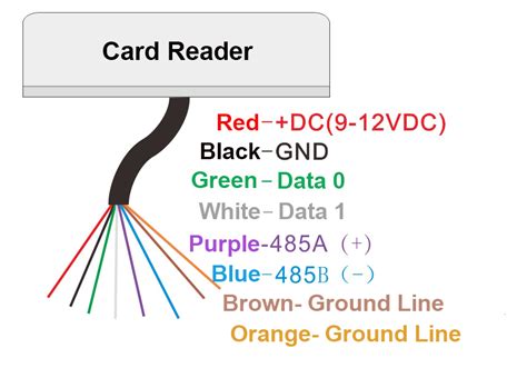
card reader access control riser diagram Understanding the wiring diagram of an access control card reader is essential for proper installation and troubleshooting. The diagram outlines the various connections and components involved in connecting the card reader to the control panel and other peripheral devices. Pakistan - Shop for Best Online at Daraz.pk Wide Variety of PC Card Reader. Great Prices, .
0 · card reader wiring diagrams
1 · access control wiring diagram
2 · access control card reader wiring
3 · access control card reader diagram
1. I am working on an Android project which relies on the unique UID of a discovered NFC tag to process the tag. I extract this UID using the following code: byte[] extraID = .
Access/Egress: Presenting an authorized card to the reader releases the lever of the locking device momentarily for access. Entry momentary unlock time is determined by the card reader .

Understanding the wiring diagram of an access control card reader is essential for proper installation and troubleshooting. The diagram outlines the various connections and components involved in connecting the card reader to the .Access/Egress: Presenting an authorized card to the reader releases the lever of the locking device momentarily for access. Entry momentary unlock time is determined by the card reader programming.
Understanding the wiring diagram of an access control card reader is essential for proper installation and troubleshooting. The diagram outlines the various connections and components involved in connecting the card reader to the control panel and other peripheral devices.
Resolution: The following common wiring diagrams are available: One Single Door with Panic Bar. Electric Latch Retraction, with Auto Operator. Delayed egress - Fire Rated Application. Auto Operator and actuator. Electric Latch Retraction with Remote Push Button - Fire Rated Application. Fail Secure electric strike and card reade r.A typical access control system set up will have these four main components: card reader/keypad, door contact, request to. exit and lock power device connectivity. What this composite cable does is to simply. Here's how it will look like with a door setup: Door Setup with Composite Cable.Product Construction: Conductor: • Stranded bare copper. Jacket: PVC. Temperature range: -20 ̊C to +60 ̊C. Individual elements marked for application (see diagram below) Blue overall jacket. Shields: • Choice between all 4 elements shielded or just the 3-pair shielded. Applications: Security systems. Access control. Card reader. Door control.
The access control system wiring diagram typically includes devices such as door readers, proximity cards, electric locks, power supplies, and control panels. The diagram shows how these components are connected and how they interact with each other to create a .Access control system with door lock, card reader and security exit button ️. Learn how to wire a basic access control system with this helpful wiring diagram. Ensure proper installation and functionality with step-by-step instructions.The access control system wiring diagram typically includes various components, such as door controllers, card readers, power supplies, electric locks, and intercoms. Each component is represented by a specific symbol or icon, making it easy .
It identifies all the components of the access control system, including the card readers, turnstiles, cameras, intercoms and biometric readers, as well as the wiring connections, AC power, alarms, safety functions, and more.t047 access control riser diagram t048 security camera riser diagram t049 elevator cab security riser diagram t050 video intercom system riser diagram security access control door diagrams t051 door type c1 - integrated card reader, single door t052 door type c1i - integrated card reader, single door, video intercom t053 doory type c1k - wall .Access/Egress: Presenting an authorized card to the reader releases the lever of the locking device momentarily for access. Entry momentary unlock time is determined by the card reader programming.Understanding the wiring diagram of an access control card reader is essential for proper installation and troubleshooting. The diagram outlines the various connections and components involved in connecting the card reader to the control panel and other peripheral devices.
Resolution: The following common wiring diagrams are available: One Single Door with Panic Bar. Electric Latch Retraction, with Auto Operator. Delayed egress - Fire Rated Application. Auto Operator and actuator. Electric Latch Retraction with Remote Push Button - Fire Rated Application. Fail Secure electric strike and card reade r.A typical access control system set up will have these four main components: card reader/keypad, door contact, request to. exit and lock power device connectivity. What this composite cable does is to simply. Here's how it will look like with a door setup: Door Setup with Composite Cable.
card reader wiring diagrams
Product Construction: Conductor: • Stranded bare copper. Jacket: PVC. Temperature range: -20 ̊C to +60 ̊C. Individual elements marked for application (see diagram below) Blue overall jacket. Shields: • Choice between all 4 elements shielded or just the 3-pair shielded. Applications: Security systems. Access control. Card reader. Door control.The access control system wiring diagram typically includes devices such as door readers, proximity cards, electric locks, power supplies, and control panels. The diagram shows how these components are connected and how they interact with each other to create a .Access control system with door lock, card reader and security exit button ️. Learn how to wire a basic access control system with this helpful wiring diagram. Ensure proper installation and functionality with step-by-step instructions.The access control system wiring diagram typically includes various components, such as door controllers, card readers, power supplies, electric locks, and intercoms. Each component is represented by a specific symbol or icon, making it easy .
smart card firma digitale camera di commercio
It identifies all the components of the access control system, including the card readers, turnstiles, cameras, intercoms and biometric readers, as well as the wiring connections, AC power, alarms, safety functions, and more.
smart card for janumet
access control wiring diagram

access control card reader wiring

This tiny micro NFC/RFID tag is super small, and contains an NTAG213 chip .
card reader access control riser diagram|access control card reader wiring