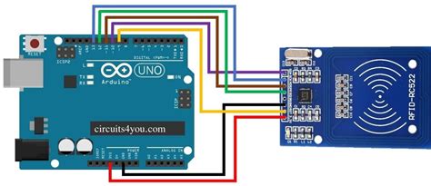
rfid tag circuit schematic RFID reader is used to activate passive tag with RF energy and to extract information from the tag. For this function, the reader includes RF transmission, receiving and data decoding sections. In addition, the reader includes a serial communication (RS-232) capa-bility to communicate with the host computer. Depend- The problems seems to be that it's not possible to emulate/modify the sector 0, .
0 · rfid with Arduino code
1 · rfid tag block diagram
2 · rfid schematic diagram
3 · rfid rc522 with arduino
4 · rfid rc522 interfacing with arduino
5 · rfid rc522 Arduino Mega 2560
6 · rfid circuit diagram explanation
7 · how to connect rfid arduino
Relay: Relays NFC traffic between two devices using a server. One device operates as a .Google Pay / Google Wallet (one or both, depending on where you are) do NOT allow cloning cards. They let you register a legitimate bank card or credit card with Google, which your phone uses for tap-to-pay. It doesn't pretend to be your card, it sends a secure token which is later .
Tags consist of a silicon device and antenna circuit. The purpose of the antenna circuit is to induce an energizing signal and to send a modulated RF signal. The read range of a tag .RFID reader is used to activate passive tag with RF energy and to extract information from the tag. For this function, the reader includes RF transmission, receiving and data decoding sections. In addition, the reader includes a serial communication (RS-232) capa-bility to communicate with the host computer. Depend-
Tags consist of a silicon device and antenna circuit. The purpose of the antenna circuit is to induce an energizing signal and to send a modulated RF signal. The read range of a tag largely depends upon the antenna circuit and size. The antenna circuit is made of a LC resonant circuit or E-field dipole antenna, depending on the carrier frequency.This section is written for RF coil designers and RFID system engineers. It reviews basic electromagnetic theories on antenna coils, a procedure for coil design, calculation and measurement of inductance, an antenna tuning method, and read range in RFID applications. 2003 Microchip Technology Inc. A well-designed schematic diagram of an RFID tag offers a detailed view of how the tag works and what kind of information it can provide. It includes a circuit board, antennas, RF receivers and transmitters, power sources, and interface ports.RFID Block Schematic: A simplified block schematic of an RFID tag (also called transponder) is shown in the diagram below. Various components of the tag are as shown. Normally, the antenna is external to the tag chip, and large in size.
In this tutorial, we discussed how the RFID Reader Module works and how we can use it with Arduino. For Interfacing RFID Reader Module RC522 with Arduino, we have provided Circuit Connection, Arduino Code, and a step-by-step guide.Learn how to interfacing RFID Reader with Arduino. Reading RFID tags and giving access. RFID pinout, Circuit, Code for RFID with ArduinoTRF7970A is a high performance 13.56MHz HF RFID/NFC Transceiver IC composed of an integrated analog front end (AFE) and a built-in data framing engine for ISO15693, ISO14443A, ISO14443B, and FeliCa.
RC522 RFID Reader Module Pinout diagram, Pin Configuration details, Interfacing with Arduino Example, Applications, Features, Datasheet.Learn the different components that go into an RFID Tag such as RFID chip, inlay, antenna and strap. Choosing the best RFID is important for any RFID project.RFID reader is used to activate passive tag with RF energy and to extract information from the tag. For this function, the reader includes RF transmission, receiving and data decoding sections. In addition, the reader includes a serial communication (RS-232) capa-bility to communicate with the host computer. Depend-Tags consist of a silicon device and antenna circuit. The purpose of the antenna circuit is to induce an energizing signal and to send a modulated RF signal. The read range of a tag largely depends upon the antenna circuit and size. The antenna circuit is made of a LC resonant circuit or E-field dipole antenna, depending on the carrier frequency.
This section is written for RF coil designers and RFID system engineers. It reviews basic electromagnetic theories on antenna coils, a procedure for coil design, calculation and measurement of inductance, an antenna tuning method, and read range in RFID applications. 2003 Microchip Technology Inc. A well-designed schematic diagram of an RFID tag offers a detailed view of how the tag works and what kind of information it can provide. It includes a circuit board, antennas, RF receivers and transmitters, power sources, and interface ports.
RFID Block Schematic: A simplified block schematic of an RFID tag (also called transponder) is shown in the diagram below. Various components of the tag are as shown. Normally, the antenna is external to the tag chip, and large in size. In this tutorial, we discussed how the RFID Reader Module works and how we can use it with Arduino. For Interfacing RFID Reader Module RC522 with Arduino, we have provided Circuit Connection, Arduino Code, and a step-by-step guide.Learn how to interfacing RFID Reader with Arduino. Reading RFID tags and giving access. RFID pinout, Circuit, Code for RFID with ArduinoTRF7970A is a high performance 13.56MHz HF RFID/NFC Transceiver IC composed of an integrated analog front end (AFE) and a built-in data framing engine for ISO15693, ISO14443A, ISO14443B, and FeliCa.
RC522 RFID Reader Module Pinout diagram, Pin Configuration details, Interfacing with Arduino Example, Applications, Features, Datasheet.
rfid pig tags
rfid with Arduino code
rfid passive tag printer

rfid tag block diagram
Enhance your gaming experience with the Super Smash Bros. Ultimate .From high-quality character figures to super-portable cards, amiibo can come in different shapes and sizes. You can tap your amiibo to the right Joy-Con™ controller's Right Stick or the NFC .
rfid tag circuit schematic|rfid circuit diagram explanation