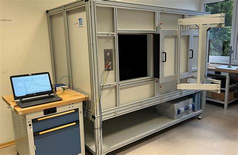
k factor rfid tags We derive a theoretical formula for RCS of an RFID tag with a minimum scattering antenna and describe an experimental measurement technique which involves using a network analyzer connected to an anechoic chamber with and without the tag. NFC Chip Customers use their phone to scan a chip embedded in your card. Their phone gets a notification with the link to your VistaConnect experience. NFC business card features Make a stronger connection with potential customers. VistaConnect gives . See more
0 · uhf rfid testing
1 · uhf rfid tag performance
2 · uhf rfid performance
3 · rfid backscatter equation
4 · backscattering rfid tags
64. This project showcases how to exploit vulnerabilities in NFC cards using Arduino and RFID technology. By leveraging the MFRC522 RFID module, you can read and write data on NFC cards. The code provided offers a foundation .
radio frequency identification (RFID) cards based on measurements of electrical resonance .We derive a theoretical formula for RCS of an RFID tag with a minimum scattering antenna and describe an experimental measurement technique which involves using a network analyzer connected to an anechoic chamber with and without the tag.radio frequency identification (RFID) cards based on measurements of electrical resonance and measurements of the energy at carrier harmonics during a reader/card transaction.In this paper, we present an overview of UHF RFID tag performance characterization. We review the link budget of RFID system, explain different tag performance characteristics, and describe various testing methods. We also review state-of-the art test systems present on the market today. Keywords: Measurement, RFID. 1.
RFID sensor tags consist of an antenna, a radio frequency integrated circuit chip (RFIC), and at least one sensor. An ideal tag can communicate over a long distance and be seamlessly integrated.1 Executive Summary. This application note shows how the Bode 100 can be used to measure the resonance frequency and quality factor of a 13.56 MHz RFID transponder tag without contacting the DUT1. Note that the same method can be applied to a different frequency range (e.g. 125 kHz) as well. Early experimenters working with item-level RFID tags have discovered that gamma radiation levels used in typical sterilization cycles can permanently damage or affect the data and electronic memory contained in an RFID tag.Tag performance can be characterized by tag sensitivity (also called threshold POTF, Power on Tag Forward) and tag backscatter (also called POTR, Power on Tag Reverse). A typical response of a T-matched tag is shown in Fig. 2 where both POTF and POTR are at tag threshold.
This circuit allows the accurate calculation of the coupling factor k between reader and tag. It can be done by using the theory of transformers. See (EM Microelectronic, 2002). Abstract: This letter focuses on 13.56 MHz high-frequency radio frequency identification (RFID) in the case of small tags detection, with an effective area below 1 cm 2. In such an identification system, based on load modulation principle, the magnetic coupling coefficient k and quality factor of the RFID reader coil are the key parameters. A high Q planar chipless RFID tag with high sensitivity is proposed for communication applications. In particular, the tag structure is composed of a complementary spiral structure (CSS) that is able to provide high sensitivity and compactness.
We derive a theoretical formula for RCS of an RFID tag with a minimum scattering antenna and describe an experimental measurement technique which involves using a network analyzer connected to an anechoic chamber with and without the tag.radio frequency identification (RFID) cards based on measurements of electrical resonance and measurements of the energy at carrier harmonics during a reader/card transaction.In this paper, we present an overview of UHF RFID tag performance characterization. We review the link budget of RFID system, explain different tag performance characteristics, and describe various testing methods. We also review state-of-the art test systems present on the market today. Keywords: Measurement, RFID. 1.
RFID sensor tags consist of an antenna, a radio frequency integrated circuit chip (RFIC), and at least one sensor. An ideal tag can communicate over a long distance and be seamlessly integrated.1 Executive Summary. This application note shows how the Bode 100 can be used to measure the resonance frequency and quality factor of a 13.56 MHz RFID transponder tag without contacting the DUT1. Note that the same method can be applied to a different frequency range (e.g. 125 kHz) as well. Early experimenters working with item-level RFID tags have discovered that gamma radiation levels used in typical sterilization cycles can permanently damage or affect the data and electronic memory contained in an RFID tag.Tag performance can be characterized by tag sensitivity (also called threshold POTF, Power on Tag Forward) and tag backscatter (also called POTR, Power on Tag Reverse). A typical response of a T-matched tag is shown in Fig. 2 where both POTF and POTR are at tag threshold.

uhf rfid testing
This circuit allows the accurate calculation of the coupling factor k between reader and tag. It can be done by using the theory of transformers. See (EM Microelectronic, 2002). Abstract: This letter focuses on 13.56 MHz high-frequency radio frequency identification (RFID) in the case of small tags detection, with an effective area below 1 cm 2. In such an identification system, based on load modulation principle, the magnetic coupling coefficient k and quality factor of the RFID reader coil are the key parameters.


why do you need a smart card reader

uhf rfid tag performance
Custom Hand Made FEW 15PCS/12PCS NFC Amiibo Card Fast Shipping! Free stickers! .
k factor rfid tags|rfid backscatter equation