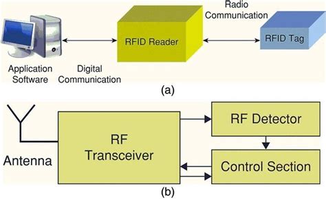
rfid reader schematic 125kHz RFID reader, EM4100 protocol tags. Contribute to Galco6/RFID-reader development by creating an account on GitHub. nfc.gov.in – NFC Driver, UDC Admit Card 2018. The Nuclear Fuel Complex Hall Ticket 2018 will be available few days before the examination. The Nuclear Fuel Complex .
0 · rfid block diagram reader
1 · rfid 125khz
2 · microid 125 rfid system
Reverse Engineering Model 3 NFC Protocol. I haven't seen any documentation online about the Tesla Model 3 NFC key card protocol yet, so I did some light digging on my .
125kHz RFID reader, EM4100 protocol tags. Contribute to Galco6/RFID-reader development .
The schematic included in this chapter is for the 13.56 MHz Reference Reader included in the .READER, INTERROGATOR RFID reader is used to activate passive tag with RF energy and to extract information from the tag. For this function, the reader includes RF transmission, receiving and data decoding sections. In addition, the reader includes a serial communication (RS-232) capa-bility to communicate with the host computer. Depend-125kHz RFID reader, EM4100 protocol tags. Contribute to Galco6/RFID-reader development by creating an account on GitHub.The schematic included in this chapter is for the 13.56 MHz Reference Reader included in the DV103003 microIDTM Developer’s Kit. The circuit is designed for short read-range applica-tions. The basic design can be modified for long-range or .
RFID Block Schematic: A simplified block schematic of an RFID tag (also called transponder) is shown in the diagram below. Various components of the tag are as shown. Normally, the antenna is external to the tag chip, and large in size.OF RFID SYSTEMS DEFINITIONS Reader, Interrogator RFID readers are used to activate passive tags with RF energy and to extract information from the tag. For this function, the reader includes RF transmission, receiving and data decoding sections. In addition, the reader often includes a serial communication (RS-232,

rfid block diagram reader
The onboard MSP430G2553 can drive a small NFC/RFID reader firmware stack that will handle basic NFC/RFID Communication. It uses SPI to communicate with the TRF7970A, as shown in Figure 1.View the TI TIDM-RFID-TRANSCEIVER reference design block diagram, schematic, bill of materials (BOM), description, features and design files and start designing.TRF79xxA HF-RFID Reader Layout Design Guide. J.Varghese. ABSTRACT. This application note describes suggested guidelines for use in the laying out the TRF79xxA family of HF RFID readers.
It is well documented and includes not only a schematic and code, but an explanation of the design considerations used during the build. The project uses an ATmega32 and the parts list priced out.Figure 1: RFid Reader. RFid Reader is powered via a development system it is connected to. The presence of the power supply is indicated by a LED marked POWER. When the RFid Reader is turned on, a 125kHz voltage is supplied on its antenna.READER, INTERROGATOR RFID reader is used to activate passive tag with RF energy and to extract information from the tag. For this function, the reader includes RF transmission, receiving and data decoding sections. In addition, the reader includes a serial communication (RS-232) capa-bility to communicate with the host computer. Depend-125kHz RFID reader, EM4100 protocol tags. Contribute to Galco6/RFID-reader development by creating an account on GitHub.
The schematic included in this chapter is for the 13.56 MHz Reference Reader included in the DV103003 microIDTM Developer’s Kit. The circuit is designed for short read-range applica-tions. The basic design can be modified for long-range or .
RFID Block Schematic: A simplified block schematic of an RFID tag (also called transponder) is shown in the diagram below. Various components of the tag are as shown. Normally, the antenna is external to the tag chip, and large in size.OF RFID SYSTEMS DEFINITIONS Reader, Interrogator RFID readers are used to activate passive tags with RF energy and to extract information from the tag. For this function, the reader includes RF transmission, receiving and data decoding sections. In addition, the reader often includes a serial communication (RS-232,The onboard MSP430G2553 can drive a small NFC/RFID reader firmware stack that will handle basic NFC/RFID Communication. It uses SPI to communicate with the TRF7970A, as shown in Figure 1.View the TI TIDM-RFID-TRANSCEIVER reference design block diagram, schematic, bill of materials (BOM), description, features and design files and start designing.
TRF79xxA HF-RFID Reader Layout Design Guide. J.Varghese. ABSTRACT. This application note describes suggested guidelines for use in the laying out the TRF79xxA family of HF RFID readers. It is well documented and includes not only a schematic and code, but an explanation of the design considerations used during the build. The project uses an ATmega32 and the parts list priced out.

rfid 125khz
The Steps: 1: Plug in you NFC reader/writer into the port on your computer. There should be a light on it that lights up red. When putting an NFC item on the platform the unit should beep and the light should turn green, removing the .
rfid reader schematic|rfid 125khz