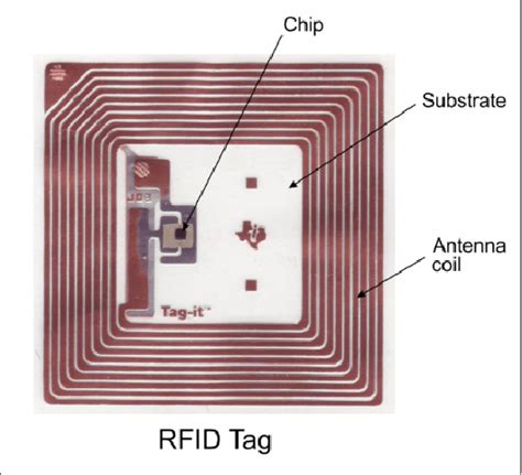
rfid tag design cst In this study, prototypes of two distinct 8-bit chipless RFID tags operating in 3–6 GHz utilising L-resonators discussed in Section 2 are reported. The chipless tags have been designed using CST Microwave Design Studio and printed on the Roger RT 5880 substrate. 25 Sample Stickers: The “25-25-25” Roll of NTAG213 Stickers (25mm circle) 12.50. .
0 · rfid tag antenna design
1 · rfid antenna design
2 · pifa rfid antenna design
Manual and automatic sending of UID of the detected card to an online database using PHP and Ajax scripts. Java Applet source code software – SDK includes an example of a uRF Series reader’s API basic implementation. The project .
The main parts of the proposed chipless MIMO tag are designed in computer simulation tool . In this study, prototypes of two distinct 8-bit chipless RFID tags operating in 3–6 GHz utilising L-resonators discussed in Section 2 are reported. The chipless tags have been designed using CST Microwave Design Studio and printed on the Roger RT 5880 substrate.
The main parts of the proposed chipless MIMO tag are designed in computer simulation tool (CST) and their performance is verified. The detailed descriptions of the component‐level design and their integration to a complete MIMO tag are examined.The design considerations for RFID tag, Impedance matching and PIFA structures are discussed in this paper. Before fabricating the actual tag, the simulation of antennaTag performance can be characterized by tag sensitivity (also called threshold POTF, Power on Tag Forward) and tag backscatter (also called POTR, Power on Tag Reverse).Dipole, Loop, and circular/Linear polarized patch antennae are the commonly used RFID antennae. One of the best illustrations of an RFID antenna is a meander dipole antenna, which is modelled in CST Studio Suite software, as shown in Fig.1
This article presents a bio-inspired circularly polarized ultrahigh-frequency (UHF) radio frequency identification (RFID) tag antenna for metallic and low-permittivity substances. This tag design is based on a leaf-shaped radiator, two shorting stubs, and slots etched on F4B substrate. The main parts of the proposed chipless MIMO tag are designed in computer simulation tool (CST) and their performance is verified. The detailed descriptions of the component-level design and their integration to a complete MIMO tag are examined.Abstract: This paper presents the design of a passive RFID tag antenna operating at 2.45 GHz. The electromagnetic simulation software called CST is used for design and simulation. A high gain (5.842dB), a good impedance matching with the microchip (-30.0 dB Return Loss) and a satisfactory read range performance (upto 5 m) was obtained.
PIFA RFID Tag Antenna Design and Simulation using CST Microwave Studio. Sudha Surwase, Dr. Ravi Yadahalli, Dr. Shankar Nawale. Abstract: There has been an enormous upsurge in the popularity of RFID (Radio Frequency Identification) systems in recent years. STM electronics has application note AN1806 with detailed description how to design and tune 13.56 antenna. And other tools - search for it. Other companies who manufacture reader and tag IC's likely have it too. In this study, prototypes of two distinct 8-bit chipless RFID tags operating in 3–6 GHz utilising L-resonators discussed in Section 2 are reported. The chipless tags have been designed using CST Microwave Design Studio and printed on the Roger RT 5880 substrate.The main parts of the proposed chipless MIMO tag are designed in computer simulation tool (CST) and their performance is verified. The detailed descriptions of the component‐level design and their integration to a complete MIMO tag are examined.
The design considerations for RFID tag, Impedance matching and PIFA structures are discussed in this paper. Before fabricating the actual tag, the simulation of antennaTag performance can be characterized by tag sensitivity (also called threshold POTF, Power on Tag Forward) and tag backscatter (also called POTR, Power on Tag Reverse).
Dipole, Loop, and circular/Linear polarized patch antennae are the commonly used RFID antennae. One of the best illustrations of an RFID antenna is a meander dipole antenna, which is modelled in CST Studio Suite software, as shown in Fig.1This article presents a bio-inspired circularly polarized ultrahigh-frequency (UHF) radio frequency identification (RFID) tag antenna for metallic and low-permittivity substances. This tag design is based on a leaf-shaped radiator, two shorting stubs, and slots etched on F4B substrate. The main parts of the proposed chipless MIMO tag are designed in computer simulation tool (CST) and their performance is verified. The detailed descriptions of the component-level design and their integration to a complete MIMO tag are examined.Abstract: This paper presents the design of a passive RFID tag antenna operating at 2.45 GHz. The electromagnetic simulation software called CST is used for design and simulation. A high gain (5.842dB), a good impedance matching with the microchip (-30.0 dB Return Loss) and a satisfactory read range performance (upto 5 m) was obtained.
PIFA RFID Tag Antenna Design and Simulation using CST Microwave Studio. Sudha Surwase, Dr. Ravi Yadahalli, Dr. Shankar Nawale. Abstract: There has been an enormous upsurge in the popularity of RFID (Radio Frequency Identification) systems in recent years.
espn nfc standings
rfid tag antenna design
afc and nfc standings 2019

rfid antenna design
Locate and tap the "Settings" app, represented by a gear icon, to access the .
rfid tag design cst|pifa rfid antenna design