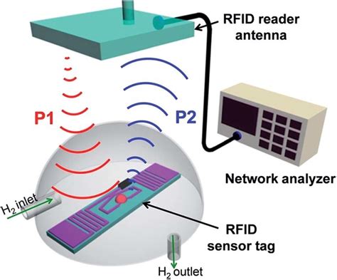
how to make a uhf rfid antenna What's involved in building your own RFID reader? As you guys would know industrial RFID readers aren't cheap, how do you energise the antenna, then read back the output?
s process.Cardholders can use Google Pay in stores, online, or in app with participating. merchants. Google Pay can be used in any stores that accept contactles. payments. To use it .
0 · uhf rfid sensor
1 · uhf rfid reader antenna design
2 · rfid reader antenna design
3 · rfid loop antenna
4 · rfid design principles pdf
5 · passive uhf tags
6 · passive uhf rfid tags
7 · 125khz antenna design
Do you have a NFC tag inquiry, need a quote or sending feedback? Send us a .
The purpose of this Instructable is to provide an easy to understand example of a Microcontroller interfacing with a UHF RFID reader. The reader we are using is the Thinkify TR-265. The demonstration consists of three UHF tags each with a unique ID. Designing an RFID antenna requires a methodical approach, starting with the selection of the operational frequency and appropriate antenna type, followed by detailed simulation and modeling to optimize its design.
The purpose of this Instructable is to provide an easy to understand example of a Microcontroller interfacing with a UHF RFID reader. The reader we are using is the Thinkify TR-265. The demonstration consists of three UHF tags each with a unique ID. Designing an RFID antenna requires a methodical approach, starting with the selection of the operational frequency and appropriate antenna type, followed by detailed simulation and modeling to optimize its design. To implement the UHF RFID reader RF front end, both an SJC board including the adaptive SJC algorithm and the ADF9010 and AD9963 board are built. The ADF9010 and AD9963 board integrated the demodulator ADL5382 as well.
What's involved in building your own RFID reader? As you guys would know industrial RFID readers aren't cheap, how do you energise the antenna, then read back the output? Antenna: The antenna is crucial for establishing communication between the RFID reader and tags. Its design and size are determined by the operating frequency of your RFID system. You can either build your own antenna or purchase one that is ready to use. RFID means Radio Frequency Identification, and radio frequencies are critical in many industries. However, it’s not very affordable to repair or even buy. Plus, its nature can be complex. So, in this article, we’ll show you how to make an easy RFID reader circuit without Arduino. Let’s begin!
In this guide, you will learn about - antenna size, indoor vs. outdoor, external antennas vs integrated antennas, frequency range options, antenna energy flow, polarization options, coupling options, gain, beamwidth, and antenna directionality. Solder a 50 Ohm surface-mount resistor at one end of the wire across the two conductors. You can use a through-hole resistor but the surface-mount resistor is neater. Either 0603 or 0805 would work well. Now simply connect the free end of the cable to the antenna connector on the receiver.They are based on quasi-static magnetic flux coupling among the reader's and tag's coils. Ultra-high-frequency (UHF, 860-860 MHz) and microwave (2.4 GHz and 5.8 GHz) systems instead involve electromagnetic interaction among true antennas and permit longer communication links, and they are the emerging technology.
We cover a lot of projects here on the Hackster blog that integrate NFC (near-field communication) or RFID (radio-frequency identification) tags. RFID, and its NFC subset, works when the radio waves emitted by the reader energize the chip’s antenna.

uhf rfid sensor
The purpose of this Instructable is to provide an easy to understand example of a Microcontroller interfacing with a UHF RFID reader. The reader we are using is the Thinkify TR-265. The demonstration consists of three UHF tags each with a unique ID. Designing an RFID antenna requires a methodical approach, starting with the selection of the operational frequency and appropriate antenna type, followed by detailed simulation and modeling to optimize its design. To implement the UHF RFID reader RF front end, both an SJC board including the adaptive SJC algorithm and the ADF9010 and AD9963 board are built. The ADF9010 and AD9963 board integrated the demodulator ADL5382 as well.What's involved in building your own RFID reader? As you guys would know industrial RFID readers aren't cheap, how do you energise the antenna, then read back the output?
Antenna: The antenna is crucial for establishing communication between the RFID reader and tags. Its design and size are determined by the operating frequency of your RFID system. You can either build your own antenna or purchase one that is ready to use. RFID means Radio Frequency Identification, and radio frequencies are critical in many industries. However, it’s not very affordable to repair or even buy. Plus, its nature can be complex. So, in this article, we’ll show you how to make an easy RFID reader circuit without Arduino. Let’s begin!
In this guide, you will learn about - antenna size, indoor vs. outdoor, external antennas vs integrated antennas, frequency range options, antenna energy flow, polarization options, coupling options, gain, beamwidth, and antenna directionality.
Solder a 50 Ohm surface-mount resistor at one end of the wire across the two conductors. You can use a through-hole resistor but the surface-mount resistor is neater. Either 0603 or 0805 would work well. Now simply connect the free end of the cable to the antenna connector on the receiver.They are based on quasi-static magnetic flux coupling among the reader's and tag's coils. Ultra-high-frequency (UHF, 860-860 MHz) and microwave (2.4 GHz and 5.8 GHz) systems instead involve electromagnetic interaction among true antennas and permit longer communication links, and they are the emerging technology.

uhf rfid reader antenna design
$7.79
how to make a uhf rfid antenna|passive uhf tags