rfid tag circuit The TID or Tag Identifier is 20 bytes or 160 bits. These means there are 1,460,000,000,000,000,000,000,000,000,000,000,000,000,000,000,000 different possible tag IDs (1.46 * 1048). More than there are atoms in the human body! Not quite the number of atoms in the universe. Every RFID tag has a . See more $8.99
0 · where to buy rfid tags
1 · what rfid tag will do
2 · what does rfid look like
3 · types of rfid systems
4 · rfid tags what are they
5 · rfid tags and their uses
6 · rfid tag system cost
7 · rfid labels how they work
Updated Tue, September 1st 2015 at 5:53 PM. List via AuburnTigers.com of radio stations across the South that air Auburn football games. Auburn Football Radio Affiliates .
The TID or Tag Identifier is 20 bytes or 160 bits. These means there are 1,460,000,000,000,000,000,000,000,000,000,000,000,000,000,000,000 different possible tag IDs (1.46 * 1048). More than there are atoms in the human body! Not quite the number of atoms in the universe. Every RFID tag has a . See moreWhile TIDs are good for absolute identification the Gen2 RFID standard was really created to replace the barcode in many retail . See moreThere are additional writable memory locations called the Access password and Kill password. The Access password can be used to prevent . See moreThe size of User Memory can vary from 0 bytes to 64 bytes. The cheaper the tag the fewer bytes of user memory it will likely have. What do you do with 64 bytes? To continue with the gallon-of-milk analogy, user memory was originally intended to record things like . See more
The RC522 module consists of an MFRC522 RFID chip from NXP. It is clocked at 27.12MHz by the onboard crystal oscillator in the 49S package. The board also consists of the .
RFID uses radio waves produced by a reader to detect the presence of (then read the data stored on) an RFID tag. Tags are embedded in small items like cards, buttons, or tiny capsules. These readers also use radio waves in some systems to write new information to the tags. The RC522 module consists of an MFRC522 RFID chip from NXP. It is clocked at 27.12MHz by the onboard crystal oscillator in the 49S package. The board also consists of the required EMI filter circuit and matching circuit. It also consists of a PCB antenna for communicating and energizing the RFID tags. RC522 RFID Reader/Writer Module Circuit .
Since the energizing and communication between the reader and tag is accomplished through antenna coils, it is important that the device must be equipped with a proper antenna circuit for successful RFID applications. Throughout this tutorial, we have covered the steps required to build and test an RFID tag, from gathering the necessary materials to assembling the circuit and programming the Arduino. By following this guide, you have gained valuable hands-on experience with RFID technology and learned how to create a practical RFID tag for various applications.
where to buy rfid tags
Learn the different components that go into an RFID Tag such as RFID chip, inlay, antenna and strap. Choosing the best RFID is important for any RFID project. While RFID accomplishes the same functionality of a barcode or magnetic strip on a credit card, it has some unique use cases that make it worth learning about and designing. In this blog, we’ll be covering how RFID works and how . RFID tags, the core components of RFID systems, come in two main types: passive and active tags. Passive RFID tags rely on external RF energy emitted by RFID readers to power their operation. These tags are cost-effective, .
In this tutorial, we learn how to interfacing RFID with an Arduino. An RFID Sensor, which is a Radio Frequency Identification Reader, gathers data from a card with an RFID tag. An RFID reader reads RFID tags. It transfers data from the card tag to an RFID reader using radio waves.
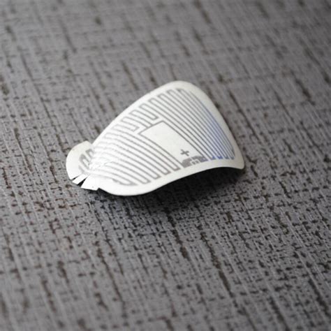
An RFID tag comes with a chip with memory to store RFID identification code, a coil and a modulator. The coil is to energise the chip when the tag is placed near an RFID reader (which also has a coil inside) via electromagnetic induction.

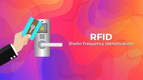
The term RFID stands for Radio Frequency Identification, as the name defines the operation of the device is based on the Radio frequency signals. The RFID systems consists of RFID Reader and a tag which is normally used in identification and tracking of objects. Before discussing more about the RFID, let’s see the uniqueness of this .RFID uses radio waves produced by a reader to detect the presence of (then read the data stored on) an RFID tag. Tags are embedded in small items like cards, buttons, or tiny capsules. These readers also use radio waves in some systems to write new information to the tags. The RC522 module consists of an MFRC522 RFID chip from NXP. It is clocked at 27.12MHz by the onboard crystal oscillator in the 49S package. The board also consists of the required EMI filter circuit and matching circuit. It also consists of a PCB antenna for communicating and energizing the RFID tags. RC522 RFID Reader/Writer Module Circuit .Since the energizing and communication between the reader and tag is accomplished through antenna coils, it is important that the device must be equipped with a proper antenna circuit for successful RFID applications.
Throughout this tutorial, we have covered the steps required to build and test an RFID tag, from gathering the necessary materials to assembling the circuit and programming the Arduino. By following this guide, you have gained valuable hands-on experience with RFID technology and learned how to create a practical RFID tag for various applications.Learn the different components that go into an RFID Tag such as RFID chip, inlay, antenna and strap. Choosing the best RFID is important for any RFID project. While RFID accomplishes the same functionality of a barcode or magnetic strip on a credit card, it has some unique use cases that make it worth learning about and designing. In this blog, we’ll be covering how RFID works and how . RFID tags, the core components of RFID systems, come in two main types: passive and active tags. Passive RFID tags rely on external RF energy emitted by RFID readers to power their operation. These tags are cost-effective, .
In this tutorial, we learn how to interfacing RFID with an Arduino. An RFID Sensor, which is a Radio Frequency Identification Reader, gathers data from a card with an RFID tag. An RFID reader reads RFID tags. It transfers data from the card tag to an RFID reader using radio waves. An RFID tag comes with a chip with memory to store RFID identification code, a coil and a modulator. The coil is to energise the chip when the tag is placed near an RFID reader (which also has a coil inside) via electromagnetic induction.
smart chip prepaid debit card

smart choices punch cards rewards 2nd grade
The Northeastern Indiana Amateur Radio Association (NIARA) is a not for profit organization of amateur (ham) radio operators located in the city of Auburn in Dekalb county Indiana. Read More. Join us on the air.
rfid tag circuit|rfid tags and their uses