how to make a redboard communicate with an rfid reader A jumper on the rear of the board labeled JP1 is closed by default allowing the board to be powered via the USB to Serial converter. By default the JP1 Jumper is closed allowing the USB to Serial converter provide power to the SRTR. Cut this jumper if you are powering the board with a LiPo battery or other external power supply. This will . See more NFC playoff picture. 1. Detroit Lions 8-1 (first place, NFC North): The Lions hold this spot for home-field advantage and the lone bye by a half-game over the Eagles going into .
0 · sparkfun simultaneous rfid reader
1 · simultaneous rfid tag reader
2 · simultaneous rfid reader
3 · redboard wiring diagram
4 · redboard wire circuit diagram
5 · redboard plus wiring diagram
6 · pcb rfid tag reader
7 · arduino redboard tutorial
CardSession requires the presence of an NFC reader, which isn’t supported in .
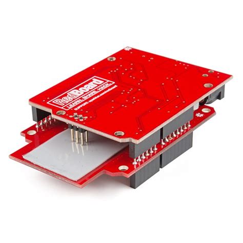
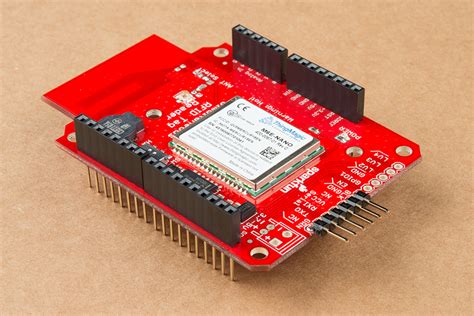
The M6E-NANO module is controlled via serial. There are two serial connections available: via a 6-pin Ftdi compatible connection and via the TX/RX pins on the Arduino shield. See moreA switch is provided to allow the user to select between Hardware Serial (HW-UART) and Software serial (SW-UART) pins on the Arduino-compatible footprint. Set this switch to SW-UARTfor all the . See more
The M6E uses an internal DC to DC converter to provide itself with power. When the EN (enable) pin is pulled low the DC/DC converter is turned off and the module does a hard reset. ENcan . See moreA buzzer is connected to pins 9 and 10 and can be PWM controlled to produce a tone. The most common use is to beep when a new tag is detected. This makes range testing much easier as you can bring the tag into the field until you hear a beep. See moreA jumper on the rear of the board labeled JP1 is closed by default allowing the board to be powered via the USB to Serial converter. By default the JP1 Jumper is closed allowing the USB to Serial converter provide power to the SRTR. Cut this jumper if you are powering the board with a LiPo battery or other external power supply. This will . See more
Introduction. The SparkFun RedBoard is an Arduino-compatible development platform that enables quick-and-easy project prototyping. It can interact with real-world sensors, control . Three questions regarding the Simultaneous RFID Reader and its accoutrements, when said reader is set up to be a shield for an Arduino, and an external UHF antenna is .Installing the CH340G driver allows your computer to recognize the RedBoard Plus as a device and lets it communicate with the board over the USB connection. You can also find the latest .
Open the example by navigating to File > Examples > SparkFun Simultaneous RFID Reader Library > Example 1 Constant Read. Select your Board and Port and click the "Upload" button. . Let's take an in-depth look at how to take multiple RFID readings at once with a SparkFun Simultaneous RFID Reader. You can accomplish this by connecting either the M7E .To communicate with a computer via USB Serial we recommend the Serial Basic or other USB UART boards. To connect, you will need to solder a 6-pin right angle header to the Serial port section of the SRTR. Note: The FTDI Cable products are known to be incompatible with the Simultaneous RFID Reader.
Introduction. The SparkFun RedBoard is an Arduino-compatible development platform that enables quick-and-easy project prototyping. It can interact with real-world sensors, control motors, display information, and perform near-instantaneous calculations.

sparkfun simultaneous rfid reader
Three questions regarding the Simultaneous RFID Reader and its accoutrements, when said reader is set up to be a shield for an Arduino, and an external UHF antenna is attached. Question 1: Simultaneous RFID Reader Our .Installing the CH340G driver allows your computer to recognize the RedBoard Plus as a device and lets it communicate with the board over the USB connection. You can also find the latest version of the CH340 drivers from WCH here .Open the example by navigating to File > Examples > SparkFun Simultaneous RFID Reader Library > Example 1 Constant Read. Select your Board and Port and click the "Upload" button. Once the code finishes uploading, open the serial monitor with the baud set to 115200. Example 1 - Constant Read. Let's take an in-depth look at how to take multiple RFID readings at once with a SparkFun Simultaneous RFID Reader. You can accomplish this by connecting either the M7E Hecto or M6E Nano directly to your computer using a USB-C connection and running Universal Reader Assistant (URA) software.
What modifications I need to do in SparkFun UHF Reader API? Is there any API available C/C++ or Python in which I could control the RID kit with the PI board? There are none supported by SparkFun and we are not aware of how to modify the existing API for use on the Pi.In this guide we'll cover everything you need to set up this RFID reader and use it with the Universal Reader Assistant application to read and write to UHF tags. We'll also cover how to set this board up in a circuit with a 3.3V microcontroller and point you to where you can get started using the SparkFun Simultaneous RFID Tag Reader Arduino .
RedBoard - Programmed with Arduino. The SparkFun RedBoard combines the simplicity of the UNO's Optiboot bootloader, the stability of the FTDI, and the shield compatibility of the Arduino R3. MCU. Bootloader. Input Voltage.
In this tutorial, we'll show you how to set up the SparkFun Simultaneous RFID Reader to take multiple, if not nearly unlimited, RFID readings simultaneously by connecting either the M7E Hecto or M6E Nano directly to your computer using a USB-C connection and running Universal Reader Assistant (URA) software, which provides a simple and .To communicate with a computer via USB Serial we recommend the Serial Basic or other USB UART boards. To connect, you will need to solder a 6-pin right angle header to the Serial port section of the SRTR. Note: The FTDI Cable products are known to be incompatible with the Simultaneous RFID Reader.Introduction. The SparkFun RedBoard is an Arduino-compatible development platform that enables quick-and-easy project prototyping. It can interact with real-world sensors, control motors, display information, and perform near-instantaneous calculations. Three questions regarding the Simultaneous RFID Reader and its accoutrements, when said reader is set up to be a shield for an Arduino, and an external UHF antenna is attached. Question 1: Simultaneous RFID Reader Our .
Installing the CH340G driver allows your computer to recognize the RedBoard Plus as a device and lets it communicate with the board over the USB connection. You can also find the latest version of the CH340 drivers from WCH here .Open the example by navigating to File > Examples > SparkFun Simultaneous RFID Reader Library > Example 1 Constant Read. Select your Board and Port and click the "Upload" button. Once the code finishes uploading, open the serial monitor with the baud set to 115200. Example 1 - Constant Read. Let's take an in-depth look at how to take multiple RFID readings at once with a SparkFun Simultaneous RFID Reader. You can accomplish this by connecting either the M7E Hecto or M6E Nano directly to your computer using a USB-C connection and running Universal Reader Assistant (URA) software. What modifications I need to do in SparkFun UHF Reader API? Is there any API available C/C++ or Python in which I could control the RID kit with the PI board? There are none supported by SparkFun and we are not aware of how to modify the existing API for use on the Pi.
In this guide we'll cover everything you need to set up this RFID reader and use it with the Universal Reader Assistant application to read and write to UHF tags. We'll also cover how to set this board up in a circuit with a 3.3V microcontroller and point you to where you can get started using the SparkFun Simultaneous RFID Tag Reader Arduino .RedBoard - Programmed with Arduino. The SparkFun RedBoard combines the simplicity of the UNO's Optiboot bootloader, the stability of the FTDI, and the shield compatibility of the Arduino R3. MCU. Bootloader. Input Voltage.

simultaneous rfid tag reader
Our custom printed NFC cards and NFC tag printing provide the perfect tap-and-go technology for improving the lives of your digitally active customers. By simplifying configuration, improving security, enabling experience, and combating forgery, NFC powers disruptive applications and customer experience around the world.MoreRFID holds an excellent reputation in the industry as one of the leading manufacturers and suppliers of NFC Cards. Established in 2008, we reserve an experience of over a decade. The primary services of the company include RFD and NFC Product .
how to make a redboard communicate with an rfid reader|redboard wire circuit diagram