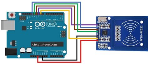
rfid chip circuit diagram Radio Frequency Identification (RFID) systems use radio frequency to identify, locate and track people, assets and animals. Passive RFID systems are composed of three components – a reader (interroga-tor), passive tag and host computer. The tag is composed of an antenna coil and a silicon chip that includes basic modulation circuitry and . $89.99
0 · rfid with Arduino code
1 · rfid tag block diagram
2 · rfid schematic diagram
3 · rfid rc522 with arduino
4 · rfid rc522 interfacing with arduino
5 · rfid rc522 Arduino Mega 2560
6 · rfid circuit diagram explanation
7 · how to connect rfid arduino
$134.007. Some GSM operators are using "NFC SIM" term to refer to a SIM card with an additional financial application. Such a card in combination with a NFC phone can be used for contactless payments. There are different options: it can act as a pre-paid debit card. your .
The RFID chip is a tiny integrated circuit that uses radio waves to store, process, .It reviews basic electromagnetic theories on antenna coils, a procedure for coil design, calculation and measurement of inductance, an antenna tuning method, and read range in RFID applications. 2003 Microchip Technology Inc. The RFID chip is a tiny integrated circuit that uses radio waves to store, process, and transfer data. With the use of an RFID chip, we can create a device that can be tracked and identified from a distance - and it all starts with the RFID chip circuit diagram.

RC522 RFID Reader/Writer Module Circuit Diagram. The Schematic diagram for the RC522 module is given below. The circuit consists of bare minimum components. As we know the main component is the MFRC522 chip.
Radio Frequency Identification (RFID) systems use radio frequency to identify, locate and track people, assets and animals. Passive RFID systems are composed of three components – a reader (interroga-tor), passive tag and host computer. The tag is composed of an antenna coil and a silicon chip that includes basic modulation circuitry and .SparkFun Qwiic RFID-IDXXLA Hookup Guide. The Qwiic RFID ID-XXLA is an I2C solution that pairs with the ID-LA modules: ID-3LA, the ID-12LA, or the ID-20LA, and utilizes 125kHz RFID chips. Let's take a look at the hardware used for this tutorial.
Radio Frequency Identification (RFID) systems use radio frequency to identify, locate and track people, assets and animals. Passive RFID systems are composed of three components – a reader (interroga-tor), passive tag and host computer. The tag is com-posed of an antenna coil and a silicon chip that includes basic modulation circuitry and non .
Learn how to use RFID NFC RC522 with Arduino, how to connect RFID-RC522 module to Arduino, how to code for RFID/NFC, how to program Arduino step by step. The detail instruction, code, wiring diagram, video tutorial, line-by-line code explanation are provided to help you quickly get started with Arduino. Find this and other Arduino tutorials on .RC522 RFID Reader Module Pinout diagram, Pin Configuration details, Interfacing with Arduino Example, Applications, Features, Datasheet. While RFID accomplishes the same functionality of a barcode or magnetic strip on a credit card, it has some unique use cases that make it worth learning about and designing. In this blog, we’ll be covering how RFID works and how .
7 Segment Display with Arduino. Components of an RFID System. RFID systems consist of three main components: the RFID tag, the reader, and the software. The RFID tag is a small device that contains a unique identifier. Tags come in various forms, including cards, key fobs, and stickers.It reviews basic electromagnetic theories on antenna coils, a procedure for coil design, calculation and measurement of inductance, an antenna tuning method, and read range in RFID applications. 2003 Microchip Technology Inc. The RFID chip is a tiny integrated circuit that uses radio waves to store, process, and transfer data. With the use of an RFID chip, we can create a device that can be tracked and identified from a distance - and it all starts with the RFID chip circuit diagram.
RC522 RFID Reader/Writer Module Circuit Diagram. The Schematic diagram for the RC522 module is given below. The circuit consists of bare minimum components. As we know the main component is the MFRC522 chip.Radio Frequency Identification (RFID) systems use radio frequency to identify, locate and track people, assets and animals. Passive RFID systems are composed of three components – a reader (interroga-tor), passive tag and host computer. The tag is composed of an antenna coil and a silicon chip that includes basic modulation circuitry and .SparkFun Qwiic RFID-IDXXLA Hookup Guide. The Qwiic RFID ID-XXLA is an I2C solution that pairs with the ID-LA modules: ID-3LA, the ID-12LA, or the ID-20LA, and utilizes 125kHz RFID chips. Let's take a look at the hardware used for this tutorial.
Radio Frequency Identification (RFID) systems use radio frequency to identify, locate and track people, assets and animals. Passive RFID systems are composed of three components – a reader (interroga-tor), passive tag and host computer. The tag is com-posed of an antenna coil and a silicon chip that includes basic modulation circuitry and non .Learn how to use RFID NFC RC522 with Arduino, how to connect RFID-RC522 module to Arduino, how to code for RFID/NFC, how to program Arduino step by step. The detail instruction, code, wiring diagram, video tutorial, line-by-line code explanation are provided to help you quickly get started with Arduino. Find this and other Arduino tutorials on .
RC522 RFID Reader Module Pinout diagram, Pin Configuration details, Interfacing with Arduino Example, Applications, Features, Datasheet. While RFID accomplishes the same functionality of a barcode or magnetic strip on a credit card, it has some unique use cases that make it worth learning about and designing. In this blog, we’ll be covering how RFID works and how .
rfid with Arduino code
rfid tag block diagram
rfid schematic diagram
$11.49
rfid chip circuit diagram|rfid rc522 Arduino Mega 2560