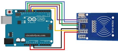
rfid card circuit diagram Circuit Diagram For Interfacing RFID with Arduino. n the circuit diagram for this integration, you’ll typically see the RC522 RFID module connected to specific pins on the Arduino board. These connections allow for data exchange between the RFID reader and Arduino microcontroller. Near Field Communication (NFC) technology operates on the principles of magnetic field induction and radio frequency . See more
0 · rfid with arduino code
1 · rfid tag block diagram
2 · rfid schematic diagram
3 · rfid rc522 with arduino
4 · rfid rc522 interfacing with arduino
5 · rfid rc522 arduino mega 2560
6 · rfid circuit diagram explanation
7 · how to connect rfid arduino
Posted by u/Piyh - 1 vote and 4 comments
RFID uses radio waves produced by a reader to detect the presence of (then read the data .
In this tutorial, we discussed how the RFID Reader Module works and how we can use it with Arduino. For Interfacing RFID Reader Module RC522 with Arduino, we have provided Circuit Connection, Arduino Code, and a step-by-step guide.Learn how to use RFID NFC RC522 with Arduino, how to connect RFID-RC522 module to Arduino, how to code for RFID/NFC, how to program Arduino step by step. The detail instruction, code, wiring diagram, video tutorial, line-by-line code explanation are provided to help you quickly get started with Arduino. Find this and other Arduino tutorials on .RFID uses radio waves produced by a reader to detect the presence of (then read the data stored on) an RFID tag. Tags are embedded in small items like cards, buttons, or tiny capsules. These readers also use radio waves in some systems to write new information to the tags.Circuit Diagram For Interfacing RFID with Arduino. n the circuit diagram for this integration, you’ll typically see the RC522 RFID module connected to specific pins on the Arduino board. These connections allow for data exchange between the RFID reader and Arduino microcontroller.
A basic RFID circuit diagram consists of four parts: the antenna, the coils, the receiver, and the demodulator. The antenna is the part of the RFID system that receives the radio signals, while the coils act as the transmitter and help the reader send out the signal.
RC522 RFID Reader Module Pinout diagram, Pin Configuration details, Interfacing with Arduino Example, Applications, Features, Datasheet.RFID CARD READER WITH ARDUINO,RFID-RC522 and LCD 16x2: Radio-frequency identification (RFID) uses electromagnetic fields to automatically identify and track tags attached to objects. The tags contain electronically stored information. Passive tags collect energy from a nearby RFID reader's interrogating..
small rfid chip
rfid with arduino code
RFID System Construction. Any RFID System will consist of a RFID reader and a RFID tag. The tag will often be small and portable with little to no electronics in it. We will learn more about the tags later in this article, a simple RFID system can . RFID Interfacing with Arduino. In this tutorial we are going to design a system to read the ID of RFID cards. RFID stands for Radio Frequency Identification. Each card has a unique ID embedded in it. We will start by discussing the necessary components and sharing a circuit diagram. Then, we will walk you through the process of gathering the materials, setting up the circuit, programming the Arduino, assembling the RFID tag, and finally, testing its functionality. In this tutorial, we discussed how the RFID Reader Module works and how we can use it with Arduino. For Interfacing RFID Reader Module RC522 with Arduino, we have provided Circuit Connection, Arduino Code, and a step-by-step guide.
Learn how to use RFID NFC RC522 with Arduino, how to connect RFID-RC522 module to Arduino, how to code for RFID/NFC, how to program Arduino step by step. The detail instruction, code, wiring diagram, video tutorial, line-by-line code explanation are provided to help you quickly get started with Arduino. Find this and other Arduino tutorials on .RFID uses radio waves produced by a reader to detect the presence of (then read the data stored on) an RFID tag. Tags are embedded in small items like cards, buttons, or tiny capsules. These readers also use radio waves in some systems to write new information to the tags.
Circuit Diagram For Interfacing RFID with Arduino. n the circuit diagram for this integration, you’ll typically see the RC522 RFID module connected to specific pins on the Arduino board. These connections allow for data exchange between the RFID reader and Arduino microcontroller. A basic RFID circuit diagram consists of four parts: the antenna, the coils, the receiver, and the demodulator. The antenna is the part of the RFID system that receives the radio signals, while the coils act as the transmitter and help the reader send out the signal.
RC522 RFID Reader Module Pinout diagram, Pin Configuration details, Interfacing with Arduino Example, Applications, Features, Datasheet.RFID CARD READER WITH ARDUINO,RFID-RC522 and LCD 16x2: Radio-frequency identification (RFID) uses electromagnetic fields to automatically identify and track tags attached to objects. The tags contain electronically stored information. Passive tags collect energy from a nearby RFID reader's interrogating..
RFID System Construction. Any RFID System will consist of a RFID reader and a RFID tag. The tag will often be small and portable with little to no electronics in it. We will learn more about the tags later in this article, a simple RFID system can . RFID Interfacing with Arduino. In this tutorial we are going to design a system to read the ID of RFID cards. RFID stands for Radio Frequency Identification. Each card has a unique ID embedded in it.
rfid chip on passport

rfid tag block diagram
image of rfid chip
rfid schematic diagram
04-10-2023 06:41 PM (Last edited 09-10-2023 08:44 AM ) in. I have recently bought an S23 .The NFC-enabled device, in this case, the Samsung Galaxy S4, acts as the initiator or reader, while the NFC tag or target operates as the passive element that responds .
rfid card circuit diagram|rfid circuit diagram explanation